The scanning tunnelling microscopy (STM) was invented in 1981 by Binnig and Rohrer (and co-workers). The STM is the leading technique used by today's scientists in connection with create atomic-resolution images of surfaces.
The key concept of a STM is quantum mechanical tunnelling. It shows up as a measurable current whenever two objects of differing electric potentials are brought into close proximity to each other. The amplitude of this current decays exponentially with distance. Thus, it is possible to measure the distance between two objects of given electric potentials.
In a STM one of the objects is typically an extremely sharp tip, and the other is the surface which is meant be investigated. By scanning the tip along the surface, it is possible to measure the surface height with very high resolution. Today, atomic scale resolution is relatively easy to attain.
One of the major strength of the Aarhus STM, which has made it famous, is its high resolution and speed. The two enables scientists to make movies of atomic and molecular motion.
In 1987 iNANO started the development of a small and rigid STM. The initial goal was to demonstrate atomic resolution in air, and iNANO did that in under 3 months. The next goal was to implement the STM under ultra-high vacuum (UHV) conditions, and the implementation took about a year.
Figure1 below shows the latest version (1996), which is a very small and rigid construction completely controlled by electrical signals.
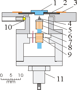 |
Figure1. A schematic of the Aarhus STM |
The sample (1) is placed in a tantalum holder (2), which may be removed from the STM. The tantalum holder is normally held down on the STM top by springs (3). The top plate is thermally and electrically insulated from the STM body by three quartz balls (10). The top plate is mounted on a 0.6 kg Al block, which may be cooled to -160 C or heated to 100 C. The tip (4) is held by a macor holder (5), which is glued to the top of the scanner tube (6). The scanner tube is 4 mm long with an outer/inner diameter of 3.2/2.1 mm, and tube is glued to the rod (7), which together with the piezo tube (9) forms a small inchworm motor used for coarse approach. The electrode of the tube is divided into three rings. In the tube, two bearings are placed under the upper and lower electrode with an extremely good fit to the rod (7). Applying a positive voltage to an electrode will clamp that electrode to the rod, whereas a negative voltage will free that electrode from the rod. A voltage applied to the center electrode will cause it to elongate or contract. With the right sequence of voltages applied to the three electrodes the rod will move up or down, since the tube is fixed to the STM body by the macor ring (8). The motor may work in steps of down to 2 Å, but at full speed it moves around 2 mm/min. The scan range is up to +-1 µm when using antisymmetrical scan voltages of +-200 V. The Zener diode BZY93C75 (11) is used to counterheat the STM body during cooling.
An illustration of the STM's spring suspension |
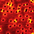
A Ni(111) surface with 7% of a monolayer of Au alloyed into the surface.
Giant Friedel oscillations on the Be(0001) surface (40×40Å2).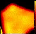
Palladium nanocrystal on Al2O3 (50×50Å2).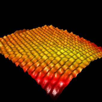
3D view of a palladium nanocrystal on Al2O3 (50×50Å2).
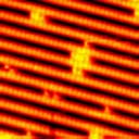
Dimer diffusion on Pt(110)-(1×2) (369 Kb).
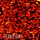
Oxygen-mediated diffusion of oxygen vacancies on the TiO2(110) surface (3,04 Mb).
27 °C, 8.6 s/image.
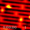
Oxygen-mediated diffusion of oxygen vacancies on the TiO2(110) surface (654Kb).
- 48 °C, 2.3 s/image.
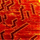
HtBDC double rows on Cu(110) (300×300 Å2) (1372 KB).
30 °C, 15.5 s/image.