With a Nanoindenter (Nano Instruments, Inc., Knoxville, TN, USA), mechanical properties of thin films can be measured. During an indentation, corresponding values of load and displacement of the diamond tip (indentation depth) are recorded, and from the resulting curve the hardness and the E-modulus are calculated. The system has load and displacement resolutions of 0.3 mN and 0.16 nm, respectively.
Figure1.
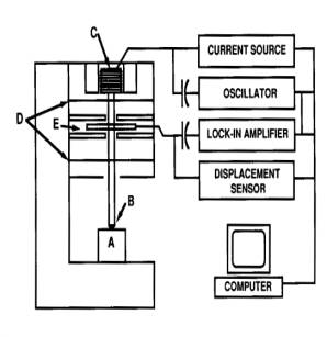
A schematic representation of the Nanoindenter is shown in Figure1. The sample is marked by A and the diamond indenter, which is shaped as a three-sided pyramid, by B. The load is applied by running a current through the load application coil (C). The created magnetic field interacts with a permanent magnet, which is mounted on the indenter shaft. The indenter displacement is measured by the capacitive displacement sensor (E). The indenter shaft is mounted on the indentation column guide springs (D).
Figure2.
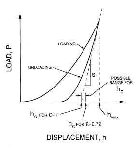
A schematic load- displacement (P- h) curve is depicted in Figure2. The plastic (permanent) deformation under the indenter is seen as a deviation of the unloading curve from the loading curve. The plastic displacement hc is found as the crossing of the x-axis of a line originating from the top of the unloading curve with the slope of the tangent of the unloading curve (S) divided by the empirical factor e (= 0.72). From a calibration curve A = A(hc), where A is the cross-sectional area of the diamond tip the distance hc from the top, A is obtained from hc. Knowing A, the hardness H = P/A can then be calculated. Finally, the E-modulus is calculated from the equation: S = dP/dh = (2/p 1/2)A1/2Er, where Er is the reduced modulus given by the equation: 1/Er = (1 - n f 2)/Ef + (1 - n I 2)/Ei. Here, n f and n i are the Poisson's ratios of film and indenter tip, respectively, and Ei and Ef are the E-modulus of the film and the indenter tip, respectively.